2.4. Remote Infrared Auditory Signage (RIAS)
Auditory cues are often used to replace some of the environmental information
that is not available to people without sight. Various technologies might
be used in the future to provide location-based auditory cues. Cameras
or digital devices (like bar code readers) might be used from a distance to
read signs and speak their message, giving information and directional cues.
Global Positioning Systems (GPS) based devices might be used to transmit
a directional auditory beacon that appears to come from a location.
This research looks at a current technical device—Remote Infrared Audible
Signage (RIAS)—that can eliminate the reliance on existing auditory cues
in the environment that is often masked and indistinct and supplement them.
Using RIAS, messages are structured and distinct, delivered in a natural
spoken language, give landmark names and spatial direction information, and
do not produce unwanted noise pollution. These auditory labels can substitute
for visual cues unavailable to the blind traveler and should increase the ease
of travel and the acquisition and accuracy of spatial knowledge. It is
hypothesized that these benefits will increase the availability of urban opportunities
and, therefore, increase the accessibility of the vision-impaired.
Remote Infrared Audible Signage technology (e.g., Talking Signs®
) was originally developed in 1979 at the Smith-Kettlewell Eye Research Institute
in San Francisco (Loughborough, 1979) . The technology has been under
continual development and evaluation at Smith-Kettlewell’s Rehabilitation
Engineering Research Center on Blindness and Low Vision (part of the National
Institute on Disability and Rehabilitation Research [NIDRR]). Talking
Signs® (TS) have found commercial deployment in numerous locations
in the US and other countries. In San Francisco, Talking Signs®
have been installed in various public and government buildings (City Hall, Courthouse,
Main Library), streetcar, subway, and commuter rail platforms, bus stops, non-profit
organizations, banks, sidewalk intersections, and even at outside public toilets.
They are installed at other cities in California (Berkeley, Freemont,
and Santa Barbara) and in other sites across the country. Talking Signs®
are installed in various countries in Europe, such as Finland, Italy, and Scotland.
Major commitments have been made in Japan; where thousands of transmitters
have been installed at street intersections, transit terminals, museums, schools,
and other locations (Talking Signs Inc., 2000, 2002) .
Audible signage can give freedom and independence to the blind and vision-impaired,
the developmentally disabled, the dyslexic, and other print-handicapped individuals,
not to mention people who don’t read the local language. The particular
audible signage system tested in this experiment consists of an infrared transmitter
that sends a directional signal to a hand held receiver that plays the transmitter’s
audio message through a speaker or an earphone. The receiver thus gives
orientation and location information to the user. The range of the signal
and the duration of the message can be adjusted to suit environmental needs.
With it, one can identify street corners, bus identification numbers
and routes, the location of bus stops, information kiosks, building entrances
and exits, and public facilities such as drinking fountains, washrooms, phones,
and elevators. In fact, any location (including those commonly identified
with a written sign) can be identified with an auditory sign. These devices
have the potential to give blind and vision-impaired people access to the information
that the sighted take for granted. They can travel independently, shop,
and visit buildings such as government offices, transit centers and rail platforms,
libraries, malls, hotels, and other large spaces, which are normally confusing
to the blind traveler. For more technical
details on the electronics of the system see Crandall, et al. (1994, 1998),
Crandall, Bentzen, & Myers (1995), and Crandall & Geary (1993) .
Figure 2.1
shows the receiver used in the present experiment. It shows the sensor
that receives the infrared signal, the speaker, “on” pushbutton,
and a breakaway neck strap. (Power and volume switch and earphone jack
not labeled). It is lightweight and easy to carry in the hand.
An infrared beam transmits the message imbedded in the sign to this hand-held
receiver, which is heard through the receiver’s speaker.
Figure 2.
1 The RIAS Receiver
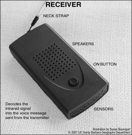
Figure 2.2 shows the appearance of the transmitter cover used at the test site.
Various designs can be used; this one is a 4” square, a truncated
pyramid covering the light-emitting diodes. It is usually mounted at
approximately seven feet above the floor to avoid interference from people and
other objects.
Figure 2.
2 Transmitter Cover and Placement
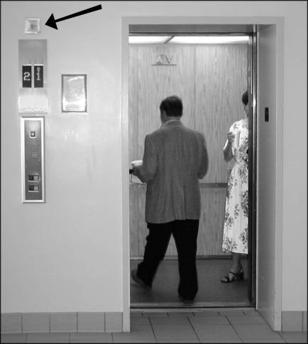
Figure 2.3
shows how the transmitter above a doorway to a building gives an identifying
signal whose message names the building. The signal is homed in on to
give the user a direct path to the labeled location.
Figure 2.
3 Directional Beam from Transmitter to Receiver
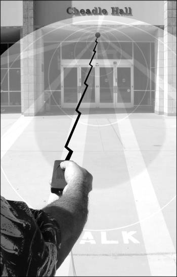
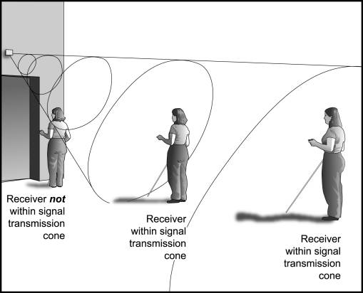
Figure 2.4
shows how the light beam forms a 51-degree cone and covers more area the further
away it shines. At a far distance, the user scans the area with the receiver
and intercepts the beam. This causes the receiver to “speak” the
verbal message imbedded in the sign. Keeping that beam aligned with the
receiver’s sensors gives a direct path to the beam’s origin.
As long as the message is heard, users know they are going directly to the correct
location. As one approaches the transmitter location, the conical beam
becomes smaller, until, up close, the user would have to point the receiver
up to find the exact location. This allows users to know when they are
“almost there.” It must be understood that this is a simplified
drawing. The conical shape comes from each diode, and there are, in this
model, 18 such diodes. Therefore, these diodes can be arrayed to fan out,
so that, in the case of a building entrance, the beam could actually cover a
180 degree area so that, no matter from which direction one is approaching,
the beam would take you directly to the source. An interior corner would
require a maximum of a 90-degrees spread, and a bus stop pole or public phone
in a plaza could have a complete 360-degree range. The actual coverage
of the beam, in both direction and intensity, is individually adjusted to fit
the environment and situation.
Figure 2.
4 Cone Shaped Infrared Light Beam from Transmitter
A person with a RIAS receiver can thus enter a new environment, such as a transit
terminal, and, by scanning around with the hand; identify different locations
from a distance and also know the direction to that location. This alone
is a great help to independent travel, but even more can be gained from such
a system.
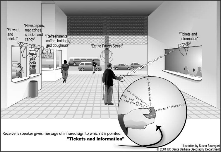
For example, Figure 2.5 shows
an installation at a train terminal. Typically, when blind people are
in an environment like this, they would have to find their way to a wall and
start to learn the locations of amenities along that wall and then check out
other walls. This is a very time-consuming activity, but this is how
most blind people learn a new environment. Whenever blind people become
disoriented in an open space, they might have to return to a wall and try to
figure out where they are and the relationship to the other locations around
them. As the diagram shows, the person using RIAS can stand in the middle
of an open space and pick up the direction and identity of distant, multiple
locations, all without moving around the environment. Instead of having
to walk to each of the locations many times to learn their spatial relationships
to each other, RIAS users have almost instantaneous feedback from the objects,
akin to using vision, and can place those relationships directly into their
cognitive map. In this illustration, the person can find the ticket window,
the exit to 4th Street, and three different concession stands.
Although it is not shown, this person would also be able to scan to the rear
of the building and find out that the doors to track #3 and #4 are directly
opposite the exit. This ability to gain almost instant knowledge of an
area is far superior to anything yet developed and holds great promise for the
blind to increase their access to environments.
Figure 2. 5 Transit Terminal Installation
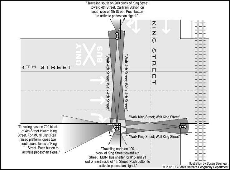
RIAS can also be used to identify street intersections, traffic flow, and signal
information. Unlike auditory traffic signals, which merely provide an
auditory signal of a certain duration during which time it is “safe”
to cross a street, Talking Signs ® go well beyond the concept
of a simple indicator. They are, in effect, an information system.
The Remote Infrared Audible Signage equivalent of an auditory traffic signal
(see Figure 2.6 ) transmits a wide beam with the name of the two streets, the
address number of the block, and the direction the receiver (person) is facing.
It can also give information about nearby places of interest and inform
if there is a push button available to change the pedestrian signal.
The narrow beam gives a distinct WALK or WAIT signal for the pedestrian traffic
in the direction the traveler is facing, as well as defining the width of a
safe passage corridor for crossing a street.
Figure 2. 6 Typical Street Information and
Coverage with RIAS